In Manchester, the Merrimack River's floodplain deposits create pockets of soft, compressible clay and loose alluvial silts that routinely surprise developers who only look at surface conditions. We have pulled SPT samples with blow counts under 4 in areas less than half a mile from Elm Street, where glacial lake sediments interlayer with modern river deposits. When you hit those conditions, traditional footings become uneconomical fast. Our stone column design approach converts that problematic profile into a composite mass that gains stiffness through controlled aggregate placement, letting you build without excavating and replacing thousands of cubic yards of material. The technique works particularly well in the Millyard district brownfield sites, where historic fill over natural soft sediment creates a two-layer problem that vibro-replacement handles effectively. Before committing to a ground improvement strategy, we often recommend confirming stratigraphy with test pits where access allows, or pairing the investigation with CPT testing to get a continuous read on tip resistance and pore pressure through the soft zone.
A well-designed stone column grid in soft Manchester silts can cut total settlement by 60 percent while doubling the soil's effective shear resistance, turning marginal land into buildable lots.
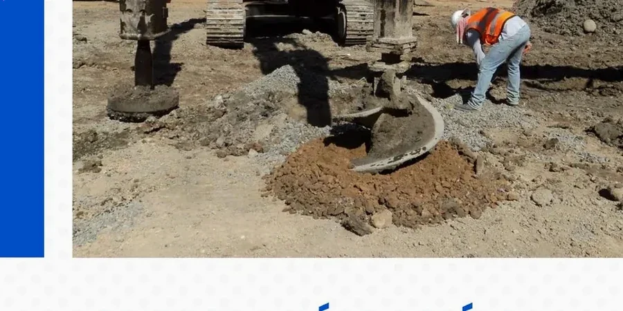
Process overview
Our design methodology follows the Federal Highway Administration's FHWA-NHI-10-025 guidelines for aggregate pier construction, cross-referenced with IBC Section 1804 for allowable bearing pressures on improved ground. For every Manchester project we calculate the replacement ratio, column spacing, and aggregate gradation based on site-specific undrained shear strength values obtained from field vane tests or triaxial testing on Shelby tube samples. A typical design sequence for the sandy silt deposits common near the airport involves estimating the improvement factor using Priebe's method, then validating it against a unit cell model in PLAXIS to confirm settlement reduction meets the structural engineer's tolerance, usually keeping post-improvement settlements under 1 inch for column loads up to 200 kips. The stone column design integrates with the site's drainage profile, since the columns act as vertical drains that accelerate consolidation of the surrounding matrix, a fringe benefit that significantly shortens the waiting period before foundation construction can begin on sites with high groundwater like those along the Piscataquog River tributary zones.
Top questions
What does stone column design cost for a typical site in Manchester?
For most commercial and multi-family sites in Manchester, the design engineering package including settlement analysis, column layout drawings, and construction specifications runs between US$1,270 and US$5,190 depending on the number of borings, the complexity of the subsurface profile, and whether dynamic or static analysis is required for liquefaction mitigation. Sites with multiple soil layers or peat interbeds require more extensive PLAXIS modeling, which pushes the fee toward the upper end of the range.
How deep can stone columns be installed in Manchester soils?
The practical depth limit depends on the vibrator horsepower and the resistance of the bearing layer. In Manchester's river terrace deposits, we typically design columns terminating in the dense glacial till or outwash sand at depths between 15 and 45 feet. Deeper installations require pre-drilling or a bottom-feed system to maintain column continuity through stiff intermediate layers. We specify the termination criteria based on CPT tip resistance or SPT blow count from the site investigation, not on a preset depth, to ensure every column reaches competent ground.
Do stone columns work for liquefaction mitigation in New Hampshire?
Yes, stone columns are effective for liquefaction mitigation in the loose, saturated sands found in Manchester's floodplain deposits. The columns densify the surrounding sand during installation through vibration and displacement, while also providing drainage paths that prevent pore pressure buildup during seismic shaking. We design the grid spacing using the factor of safety against liquefaction computed from SPT or CPT data per the Idriss and Boulanger procedure, then specify a replacement ratio that brings the post-treatment factor of safety above 1.3 for the design earthquake specified in ASCE 7.