← Home · Slopes & Walls

Retaining Wall Design for Manchester’s Glacial Soils

Together, we solve the challenges of tomorrow.

LEARN MORE →

Manchester’s growth from a textile powerhouse along the Merrimack River into a modern New England hub left a patchwork of fill, dense glacial till, and sensitive marine clays beneath the city. Anyone who has excavated near Elm Street or the old millyard district knows the ground can change within a few feet. A retaining wall design here is not a catalog detail. The loading from saturated varved silts, the freeze-thaw cycles that chew on poorly drained backfill, and the lateral squeeze from ice-lensed soils demand a geotechnical approach that reads the site before it draws a single line. We combine subsurface data from test pits and lab classification to map where the competent bearing stratum actually sits, so the wall section is neither overbuilt nor skating on a thin crust of weathered drift over soft lake-bottom sediment.

A retaining wall in Manchester is only as good as the assumption about what sits beneath the footing — glacial till does not read the plans.

Methodology and scope

The most common mistake we see in Manchester is a contractor setting a cast-in-place cantilever wall on a footing bearing in what looks like firm brown till, only to discover it is a three-foot lens of desiccated crust over gray, high-plasticity clay that softens with the first spring thaw. The wall rotates, the backfill settles, and the sidewalk above develops a crack that the city tags within a month. A proper retaining wall design starts with quantifying drained and undrained shear strength at the actual footing elevation and checking global stability for the deepest plausible groundwater table, not the one you measure on a dry Tuesday in August. When bedrock is shallow, as it is in parts of the Heights, we often pair the wall analysis with a slope stability model to confirm the cut face holds during construction before the wall is even poured.
Retaining Wall Design for Manchester’s Glacial Soils
Technical reference image — Manchester New Hampshire

Local geotechnical context

We investigated a 14-foot-high segmental block wall behind a commercial building off South Willow Street where the owner had skipped the subsurface exploration to save a few hundred dollars. The wall was founded on loose sandy silt with lenses of organic matter from an old filled-in drainage swale. After two winters, the entire middle third had bulged outward nearly five inches and the geogrid reinforcement was pulling through the blocks. The fix required dismantling the wall, over-excavating the soft zone, and rebuilding with a reinforced concrete cantilever keyed into competent glacial till. That remediation cost more than triple what the original design and a proper CPT test would have run. Manchester has too many buried swales, old mill foundations, and undocumented utility trenches to guess at subsurface conditions. The cost of getting it wrong in a city with a real frost line and aggressive snowmelt is not a risk you want to carry into a building permit.

Need a geotechnical assessment?

Reply within 24h.

Email: contact@geotechnical-engineering.vip

Reference parameters

ParameterTypical value
Design earth pressure distributionAt-rest (Ko) or active (Ka) per wall movement tolerance
Backfill friction angle (Ø')30° to 38° typical for granular NHDOT 209.2 borrow
Undrained shear strength (Su) for clay500 to 2,000 psf in varved lacustrine deposits
Global factor of safety (sliding)1.5 minimum per IBC 1806.1
Seismic coefficient (kh)0.10 to 0.15 per ASCE 7-22 Site Class D/E
Bearing capacity verificationGeneral shear or punching per Vesić method
Drainage system requirementContinuous blanket drain + weep holes at 5 ft o.c. minimum

Complementary services

01

Cantilever and Counterfort Design

Reinforced concrete walls for cuts over 10 feet, analyzed for overturning, sliding, and bearing with site-specific soil parameters from our accredited lab program.

02

Segmental Block Wall Evaluation

Geogrid-reinforced MSE walls with internal and external stability checks per FHWA guidelines, adapted to Manchester's glacial soils and frost depth requirements.

03

Global Stability and Backslope Analysis

Slope stability modeling in Slide2 or SLOPE/W to confirm the wall and retained soil mass work as a single stable system, especially where the backslope exceeds 2H:1V.

04

Construction-Phase Monitoring

Inclinometer and survey monitoring during excavation and backfill placement to confirm wall deflections stay within the design assumptions and IBC tolerances.

Reference standards

IBC 2021 Chapter 18: Soils and Foundations, ASCE 7-22 Minimum Design Loads for Buildings and Other Structures, ASTM D1586 Standard Test Method for Standard Penetration Test (SPT), NHDOT Standard Specifications for Road and Bridge Construction, Section 209

Frequently asked questions

What is the typical cost range for a retaining wall design in Manchester NH?

For a standalone retaining wall design with a site visit, subsurface data review, and stamped calculations, the fee typically runs between US$920 and US$4,000. The range depends on wall height, whether we need to run a slope stability model, and if new borings or test pits are required to supplement existing data.

Do I need a retaining wall design for a wall under 4 feet?

Strictly speaking, the IBC exempts walls under 4 feet from requiring a building permit in many cases, but that exemption assumes no surcharge and no sloping backfill. In Manchester, where frost action in silty backfill can easily heave a small wall out of alignment, we still recommend a basic geotechnical review for any wall retaining more than 3 feet of soil, especially if it is adjacent to a driveway or property line.

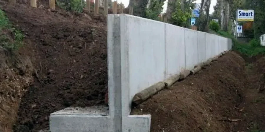
How do you handle groundwater behind the wall in Manchester's soils?

The glacial till and varved clay deposits around the Merrimack valley tend to perch water, so we specify a continuous granular drainage blanket behind the wall with a perforated collector pipe at the footing level, daylit or connected to a storm system. We also design the wall for a hydrostatic pressure case if the drain clogs, because in a Manchester winter, a frozen weep hole is a guaranteed headache.

What is the design life of a properly designed retaining wall?

A cast-in-place concrete retaining wall designed to IBC and ACI 318 standards, with proper drainage and concrete cover for New England exposure, should have a service life exceeding 50 years. The key driver in Manchester is the freeze-thaw durability of the concrete and the long-term performance of the drainage system, not the structural capacity of the steel.

Location and service area

We serve projects in Manchester New Hampshire and surrounding areas.

View larger map